Summers in North America are always a fun, action packed time of year.
For me, the summer officially begins early with a visit to Maker Faire, where I am inspired by the weird and wonderful creativity on display.
For example, this 5-story tall fire-breathing robot:

This year I took inspiration from one of the smaller, (sadly) non fire-breathing IoT projects I noticed and decided to create something interesting for the San Mateo Street Festival – every year in Downtown San Mateo we host a booth for my wife’s Taekwondo business and do our best to stand out from the crowd.
The Idea
Create a digital equivalent to the strongman game often found at carnivals where instead of swinging a sledge hammer at a target near the ground, the objective is to kick a target.
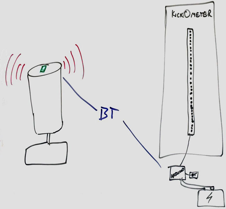
On the whiteboard it looks something like this:

On the left hand side is a Wavemaster (free-standing kicking target commonly found in martial arts facilities) and a phone MacGyvered on top with duct tape.
On the right hand side is an Arduino connected to a Bluetooth module, a digital LED strip and a power source, mounted on a scoreboard.
The logic is fairly simple:
- App on phone establishes a Bluetooth connection to the Arduino and monitors its accelerometer
- Someone kicks the target, force is calculated and this value is sent to the Arduino via Bluetooth
- Arduino receives the value, lights up the appropriate number of LEDs
- Person that kicked the target basks in the glory of their score 🙂
Electronics
Below is the list of materials I used for the electronics side of the project.
It needed to be portable and work without mains power all day, so I opted for a beefy USB portable power supply. A Type-M female adapter for power input on the LED strip was a convenient way to support both mains and portable power.
- Arduino Uno
- Adafruit NeoPixel Digital RGB LED Strip (30 LEDs)
- Sparkfun BlueSMiRF Silver Modem
- 470 Ohm resistor
- 1000 uF capacitor
- An old USB cable
- 1 Type-M male connector
- 1 Type-M female connector
- Lumia 635 (running Windows 10)
- USB portable power capable of 2A/5V. I went a little overboard and got a really good, although much larger option than I really needed by Anker
- Male header pins (6 pins wide)
- Misc. wires including female-to-male jumpers will simplify some of the connections
Assembly
Three things need to happen to assemble the hardware correctly for the scoreboard:
- Connect the LED strip to power
- Connect the LED strip to the Arduino data and ground pins
- Connect the RX, TX, VCC and GND of the Bluetooth board to the appropriate Arduino pins
Connecting the LED strip to power
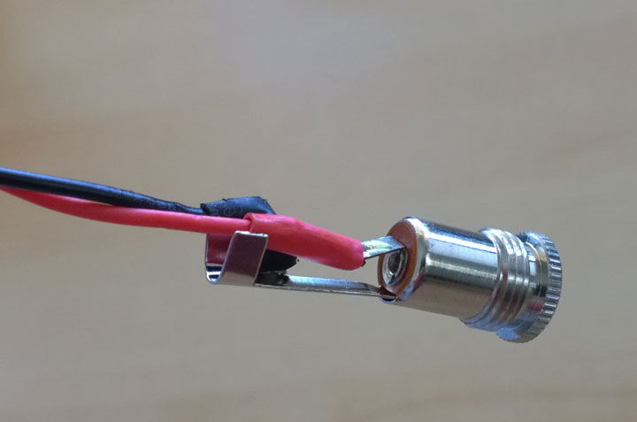
Solder a red wire to the 5V and a black wire to the GND. In parallel across these wires, connect the 1000 uF capacitor before connecting the wires to the Type-M female connector.
I went with a polarity of positive inside the terminal and negative outside the terminal as this was consistent with the DC power supply I was using during testing.

A second wire from the GND needs to be connected to the GND on the Arduino. Cutting a male-to-male jumper cable in half and soldering the wire end to the GND was a simple solution for this.
Connect the LED strip to the Arduino data and ground pins
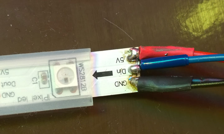
Next, check the direction of the arrows on the LED strip, they need to point away from the Din that the data wire needs to be soldered to.

I chose to solder a blue cable here, which needs to have the 470 Ohm resistor wired inline before connecting to Digital Pin 6 on the Arduino – a different pin can be used if desired, the Sketch will need to be modified to use this other pin in this case.
Connect the Bluetooth board to the Arduino
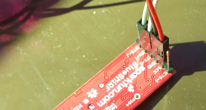
I found the simplest way to connect wires to the board was to solder in a 6 pin male header then connect female jumpers.

The mapping from the Bluetooth board to the Arduino is as follows:
- VCC -> 5v on Arduino
- TX -> RX on Arduino
- RX -> TX on Arduino
- GND -> Digital GND on Arduino
That’s pretty much it for the electronics!
In the next post, I’ll discuss the software running on both the phone and the Arduino.